An introduction to Geometric Dimensioning & Tolerancing (GD&T)
This is a blog post from Spencer Strouse, Director of Engineering at DCS. Geometric Dimensioning & Tolerancing (GD&T) is a tool engineers use to make sure parts fit and work together the way they should. It’s like a shared language that helps designers, builders and inspectors all understand exactly how precise each part needs to be.
The common abbreviation for Geometric Dimensioning & Tolerancing: GD&T can be a very intimidating field to get into. Where do I even begin? What are all these symbols? This is an understanding feeling to have when learning a new technical skill! My goal, in under 1000 words, is not to teach you everything about GD&T, but to give you a primer on why it is important and how to view its place in the Engineering process.
Reading a Feature Control Frame
I think of GD&T as a language. The individual symbols and numbers are the words and letters, but the Feature Control Frame (FCF) is the sentence. Everything that I need to know about the allowable variation on a feature, I’m told through the FCF. An example of a FCF is shown below:
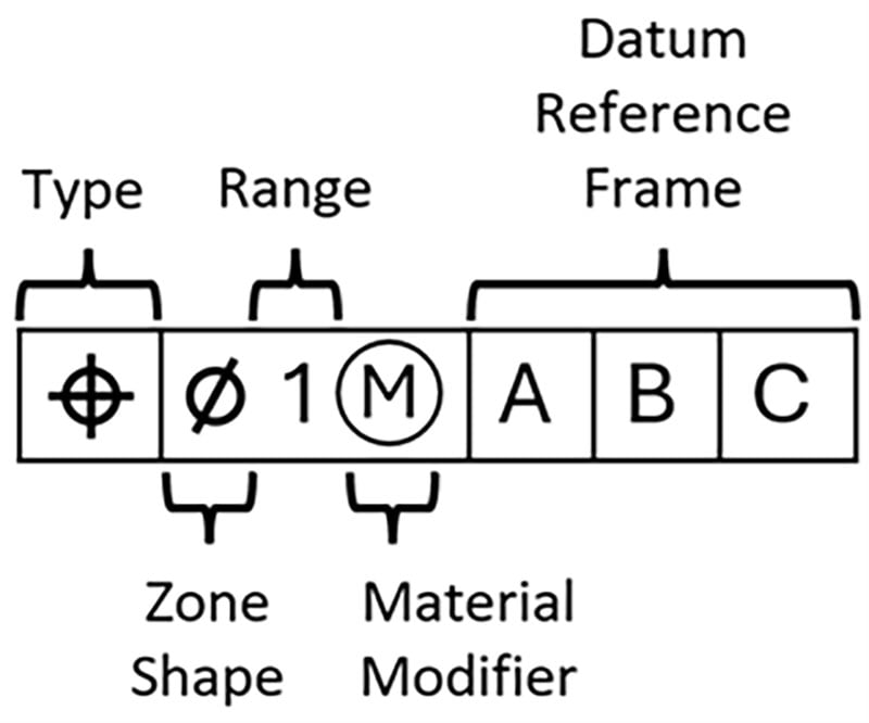
Just like with any other language, if you’re new to it then it is best to break down the sentence into its individual parts.
GD&T type
Per the latest GD&T industry standards, there are twelve possible symbols for type. However, they are not all created equal! By far, the two most common and important symbols are Profile and Position. The common uses of those are shown below:
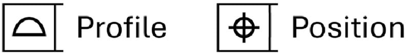
Typically speaking, a Profile tolerance controls the location of a surface and a Position tolerance controls the location of a hole or pin.
Zone shape
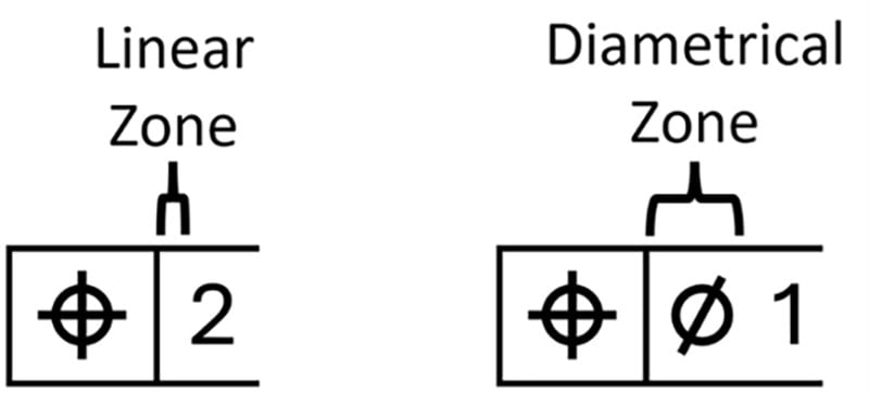
The Zone Shape is very simple and typically treated as a given in GD&T. The two common zone types are linear (1D) and diametrical (2D). If no zone is specified it means the zone is linear. If the diametrical symbol is used, then the zone is diametrical. An example of each is below:
Range
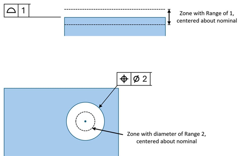
Another simple one. The Range simply dictates how imperfect a feature can be relative to its “perfect” or nominal location. The number indicates the size of the entire zone which the feature must end up within, split equally about the nominal location. An example of a Profile zone and a diametrical Position zone are shown below:
Material modifier
The material modifier is a bit confusing and won’t be covered in its entirety here (that could be a blog post in itself!). When you hear the concept of “Bonus Tolerance,” this is what they’re talking about. There are three possible material modifiers in an FCF, I’ll cover the idea of each one without getting bogged down in the specifics.
Regardless of Feature Size (RFS) means that regardless of the feature’s size, there will be no bonus tolerance applied. The range you see in the FCF is the requirement on all parts. Unless otherwise specified with the symbol of another material modifier, all FCFs are assumed at RFS.
Maximum Material Condition (MMC) means that some bonus tolerance will be allotted if the feature is not at its Maximum Material Condition. In layman’s terms, this means that if a hole is larger than the smallest allowable size, or a pin is smaller than the largest possible size, then the allowable zone increases. The feature is allowed to be “less perfect.” MMC is much more common than its counterpart discussed below. The MMC symbol is an M with a circle around it.
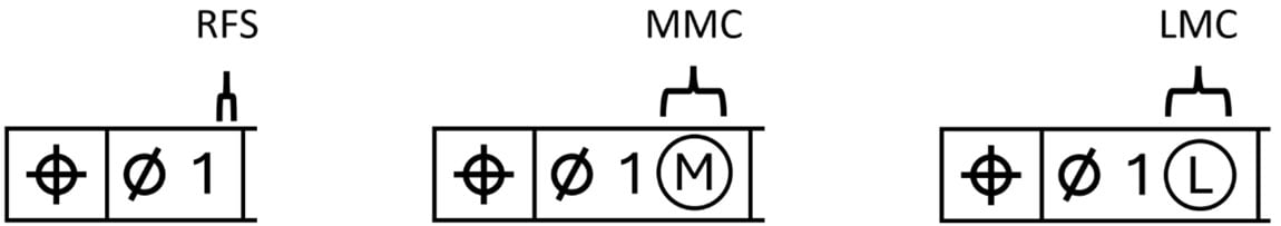
Least Material Condition (LMC) is the inverse of MMC. The bonus tolerance is allotted if the feature is not at its Least Material Condition. For holes this is the largest allowable hole. For pins this is the smallest allowable pin. The LMC symbol is an L with a circle around it.
Datum Reference Frame
The Datum Reference Frame (DRF) is the most important part of the FCF. Throughout the earlier sections I used the term “perfect” or nominal location. This location is, obviously, the target for any given feature… but how do we determine where the nominal location is? When looking at the CAD, it’s simple. Once the part is manufactured however, it is much harder to determine where nominal would truly be. The nominal location is relative to what? The answer to that simple question is the DRF. The DRF is a combination of features (called Datums) which establish the coordinate system that other features must be measured back to. An example of a simple DRF and the coordinate system established in 3D space are shown below:
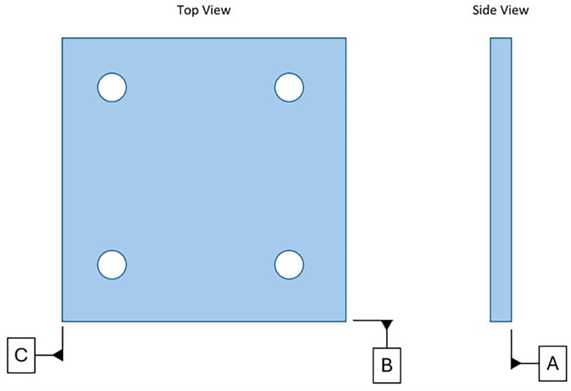
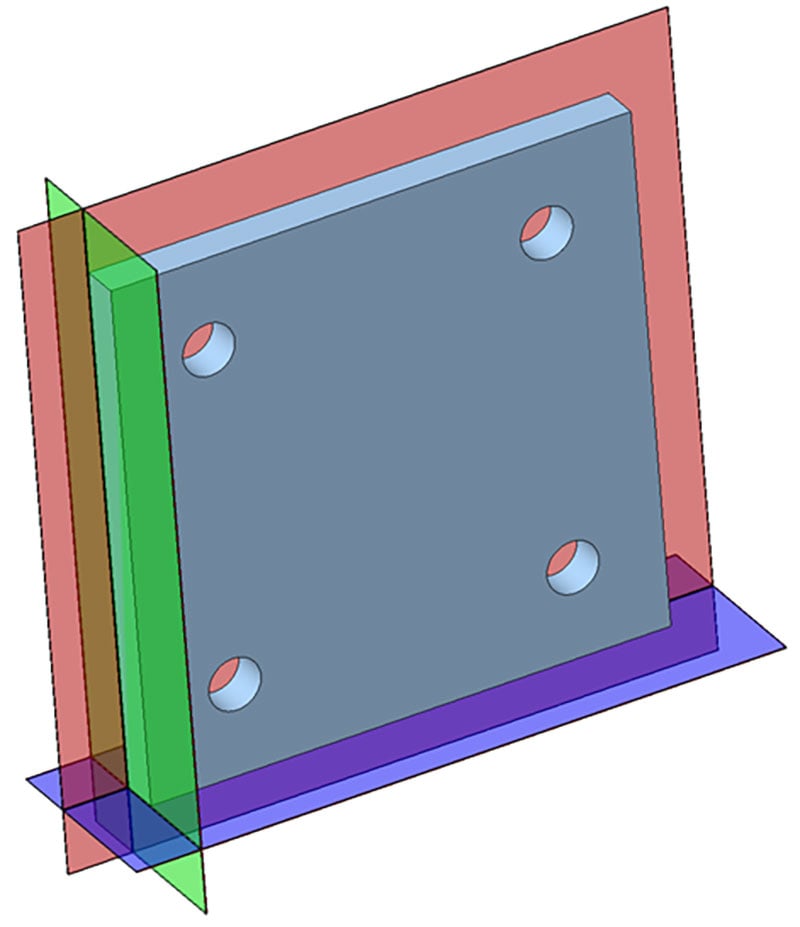
Using these three planes, we have established the coordinate system with which we can measure any other feature and determine how perfect or imperfect it is. The complexity of DRFs can run very deep, but the function is always the same as this simple example above. If we are measuring the location of a feature we need to answer the question “Relative to what?” and the DRF is the answer to the question.
Reading a Feature Control Frame - Revisited
Revisiting our example from above:

We can now read this left to right as:
This feature is controlled by a Position tolerance (Type) with a diametrical zone (Zone Shape) with a diameter of 1 (Range) at MMC (Material Modifier) relative to A|B|C.
Conclusion
The field of GD&T is vast, but all GD&T follows the principles outlined in what you’ve read. Just like any language, you need to understand the basics of sentence structure before leaping into confusing terms or vocabulary. I hope reading this can serve as a jumping off point so that your next step into the world of GD&T is a bit less intimidating.
Thanks for reading!